
Solution
Before starting this example, we encourage you to familiarize yourself with a brief theoretical introduction on the previous page.
We calculate the support reactions and draw the moment diagram. Then, we replace the actual beam with a fictitious beam and load it accordingly.
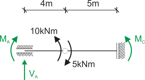 \begin{aligned} &\sum M_B^P=0\\ &5-M_C=0\ \Rightarrow M_C=5\ kNm\\ &\sum M_B^L=0\\ &M_A-10=0\ \Rightarrow M_A=10\ kNm\\ &\sum y=0\\ &V_A=0\\ \end{aligned}
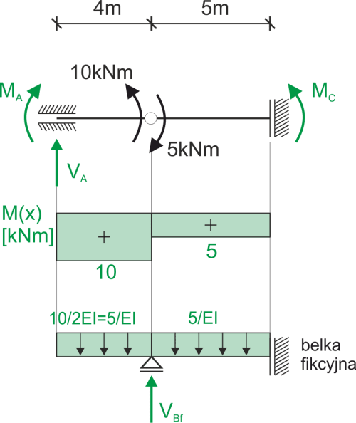
Fictitious beam
\begin{aligned} &\sum y=0\\ &V_{Bf}-\frac{5}{EI}\cdot 9=0\\ &V_{Bf}=\frac{45}{EI}\\ \\ &w_B=M_{fB}=-\frac{5}{EI}\cdot 4\cdot 2=-\frac{40}{EI}\\ &w_C=M_{fC}=-\frac{5}{EI}\cdot 9\cdot 4.5+\frac{45}{EI}\cdot 5=\frac{22.5}{EI}\\ \end{aligned}Cross-section characteristics, bending stiffness EI
\begin{aligned} &E=200 GPa\\ &I=\frac{0.15\cdot 0.2^3}{12}=1\cdot 10^{-4}\ m^4\\ &EI=(200\cdot 10^9\cdot 1\cdot 10^{-4})\cdot 10^{-3}=20,000\ kNm^2\\ \end{aligned}Calculating the desired displacements
\begin{aligned} &w_B=-\frac{40}{20,000}=-2\ mm\\ &w_C=\frac{22.5}{20000}=1.125\ mm\\ \end{aligned}
If you have any questions, comments, or think you have found a mistake in this solution, please send us a message at kontakt@edupanda.pl.